As I’ve been building more ergonomic keyboards, I kept getting the same question: “How exactly are your keyboards built?”
This post is my answer - a Ferris Sweep build log. I’ll show the process step by step so you can understand what goes into the build and what to watch out for.
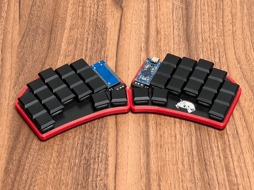
This build log is based on a Ferris Sweep Compact build — my “take to the office” keyboard: tiny, split, low‑profile, and easy to throw into a backpack.

If you want the broader context (why 34 keys, how layers work, and what daily use feels like), check these posts too:
- 30% Keyboard Club – Ferris Sweep Review
- 34 Keys as a Daily Driver for Developers
- Ferris Sweep EKI Review
Parts List (Ferris Sweep Compact)
Every build log starts with the parts. Here’s what I used.

Main parts
- Switches: 34× Kailh Choc v1 (low profile)
- Keycaps: 34× compatible with Kailh Choc
- PCBs: 2× Ferris Sweep Compact v1 (double‑sided)
- TRRS jacks: PJ320A
- Reset buttons: 2× small 2‑pin tactile reset switches (3×6×5mm)
- Controllers: 2× Arduino Pro Micro compatible controllers
- Case: 3D‑printed case dedicated to this PCB (PLA+)
- Foam under PCB: 2mm self‑adhesive foam cut to the case shape
- TRRS cable
- USB cable: matching your Pro Micro (I like magnetic cables)
Tools / consumables
- Soldering station
- Solder (I prefer ~0.56mm)
- Very strong double‑sided tape (I like the thick carpet-style tape)
Step 1: Soldering the Components
In this step we solder all required components to the PCB halves.
1) Solder the pin headers to the Pro Micro
I usually start by soldering the pin headers (“goldpins”) to the Pro Micro.

Tip: Insert the pin headers into the PCB first, then place the Pro Micro on top and solder.
This keeps everything straight and guarantees the controller fits perfectly.
2) Solder the TRRS jack and reset button
Next, solder the reset button and the TRRS jack to each PCB half.

3) Solder the Pro Micro to the PCB
Finally, solder the Pro Micro onto the PCB and cut off any protruding pin header ends.

Step 2: Flashing QMK and Testing
Flash firmware (QMK)
I usually flash my keyboards from the command line, but that’s not required.
You can also configure your layout on web page and flash firmware using tools like QMK Toolbox.

Test before soldering switches
This step looks optional — but it saves headaches.
I’ve learned the hard way that desoldering switches (especially Chocs) is annoying and expensive. So I always spend a few minutes to test every key position on the PCB before committing to switch soldering.


Step 3: Solder the Switches
Once everything works (controllers + TRRS + reset), it’s time to solder the switches.

After soldering, I do a full test again to confirm:
- all switch joints are good
- all switches are functional
Assembly (Case + Foam + PCB)
The assembly is simple: for each half you have 3 layers:
- case
- foam
- PCB with soldered components and switches
1) Apply the double‑sided tape inside the case
I line the inside of the case with strong double‑sided tape. The thick “carpet tape” holds extremely well.
2) Stick the 2mm foam to the case
Place the foam on the tape and make sure the adhesive side is facing up (so the PCB will stick to it).
3) Stick the PCB into the case
The foam helps level out solder joints and unevenness so the PCB sits flush with the case edges.
4) Install keycaps and you’re done

Practical Tips (What Helps Me)
- Soldering Pro Micro headers: Use the PCB as a jig (headers first, then Pro Micro) so everything stays aligned.
- TRRS jacks: Test the jack mechanically before soldering (make sure the plug inserts smoothly). I’ve had to desolder faulty jacks where internal contacts were bent.
- Test early: Flash + test controllers before soldering switches. It’s faster to fix problems at this stage.
- Tape cleanup: Cut tape away from your keyboard parts. Small sticky leftovers are hard to remove and look bad (especially on white cases).
- Clean your desk: After cutting tape and foam, clean the workspace — those tiny sticky bits get everywhere.
Troubleshooting split connection
If each half works on its own but doesn’t work when connected together, it’s not always a soldering issue. Some controllers need split USB detection settings in ferris/sweep/config.h:
#define SPLIT_USB_DETECT
#define SPLIT_USB_TIMEOUT 2000
Conclusion
That’s it — my Ferris Sweep build log from parts to a finished board.
If you have questions or want me to expand this guide (e.g., firmware workflow, troubleshooting, or parts alternatives), tell me what would be most useful.
☕ Support
Enjoy the insights, guides and reviews? Buy me a coffee to fund more ergo-keyboard research and guides.
Thanks for reading!
Bartosz